Thanks for sharing all of your research
The Baofeng RD5R is known to not have very good RF performance, because of its hardware design.
I don't have a schematic, but people have told me the design is similar to the Baofeng dual band FM radios, where there is only one PA for both VHF and UHF , and only one receiver RF section.
I think the radio uses a switchable RF filter near the antenna, to reduce the harmonics from VHF being produced on UHF.
I'm not an RF design expert, so I can't explain the spikes at 10kHz spacing
I'm a bit surprised that the OpenGD77 firmware produced a cleaner signal than the official firmware.
I think that would need to be re-tested, because the only possibly difference would be calibration values, and the calibration functionality that was originally written my Kai DG4KLU should be a identical to the calibration functionality of the official firmware.
If anything, I would expect the OpenGD77 firmware to be worse than the official firmware, because its possible that Kai did not find all the necessary calibration adjustments that needed to be applied to the C6000 DMR chip and the AT1846S RF chip.
Perhaps the OpenGD77 firmware omitted some calibration setting, but the default setting in the AT1846S was better than the value set by the official firmware.
Re: Spikes on Tx start.
I would not be surprised if this occurs. The voltage stabilisation in the GD77 is much better than the RD5R, but when the Tx is triggered there will be a drop in voltage until the regulator can compensate.
I think the PA / finals voltage is directly from the battery, but the driver stages are probably stabilised.
If you look at the RD5R when its running the OpenGD77 firmware on DMR, we definitely have a problem with the DMR power pulse envelope.
RD-5R OpenGD77
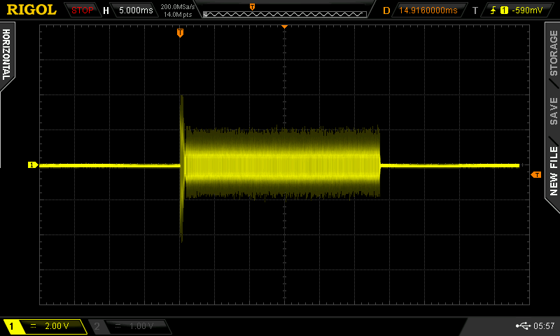
- OpenGD77 DMR pulse
- rd5r_open.png (42.72 KiB) Viewed 4284 times
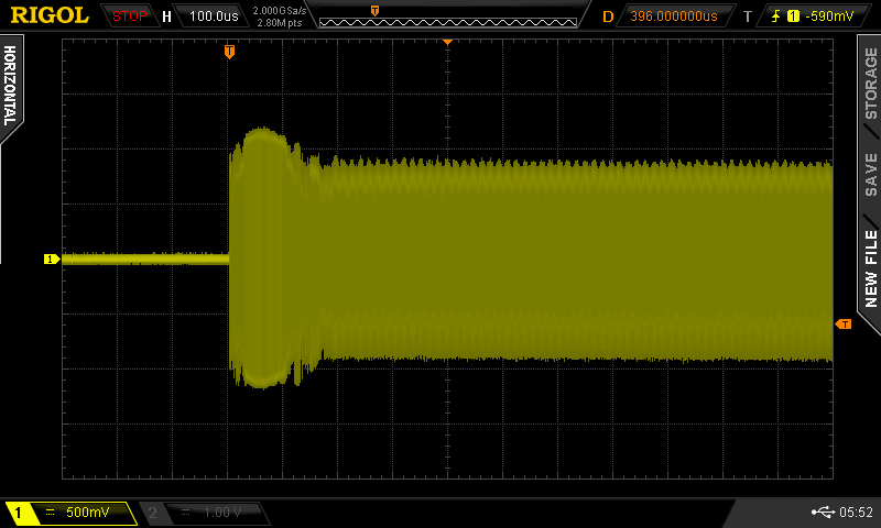
RD-5R Official
(Note the timebase is different to focus on the beginning of the pulse)

- Close up of official firmware DMR pulse
- rd5r_official.png (43.98 KiB) Viewed 4284 times
Compared with the GD77
GD-77 OpenGD77

- GD77 running OpenGD77
- open_full_1w.png (36.2 KiB) Viewed 4284 times
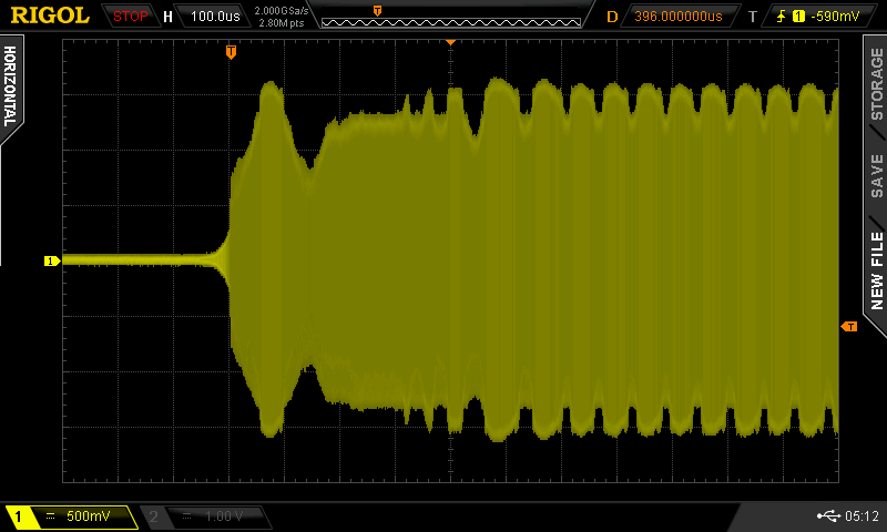
And the DM1801
DM1801 - OpenGD77
- DM1801 OpenGD77
- dm1801_open.png (44.04 KiB) Viewed 4284 times
Which although not as good as the GD77, is actually better than the official Baofeng DM1801 firmware
- DM180 - official Baofeng firmware
- dm1801_official.png (71.04 KiB) Viewed 4284 times
The control of the PA etc is identical for all radios.
https://github.com/rogerclarkmelbourne/ ... #L680-L710
So I think probably the official RD5R firmware does not turn of everything during the alternate TS.
One possibility is that the official firmware leaves the PA enabled, but only turns off the Tx from the RF chip (AT1846S) or possibly even just sets the RF output from the RF chip to 0mW
However, its not a simple change the code, to test this experiment, because we must not enable the Rx Pre-Amp when the PA is enabled, or the radio will be damaged.
So probably the first test would be to modify the code, so that the RF Pre-Amp is never enabled, then it would be safe to test some changes to Tx, e.g. In the activateRx() function, only disable the PA if the PTT is released.
BTW. The DMR chip controls the CPU to change the radio hardware from Tx to Rx, rather than the firmware actively controlling this.
i.e the firmware sends a command to the C6000 DMR chip to transmit , or receive, on the next TS, but the C6000 then tells the CPU when to actually turn on the Tx or Rx.
Although there are separate commands from the C6000 to the CPU, for Tx and Rx; The C6000 sends the command for Rx to mean end Tx.
i.e There is a command from the CPU to the C6000 for "Do Not Tx or Rx on the next TS", but the C6000 still sends the Rx command to the CPU and the end of the transmitted TS, to tell the CPU to turn off the transmitter hardware, even though it does not require the Rx hardware to be enabled.